Vertical
products filtering
Ansi
Inches
Clamp
Torque
Showing all 35 results
-

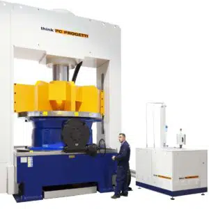
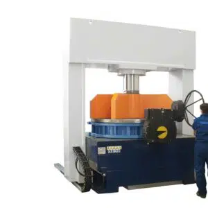
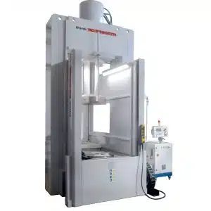
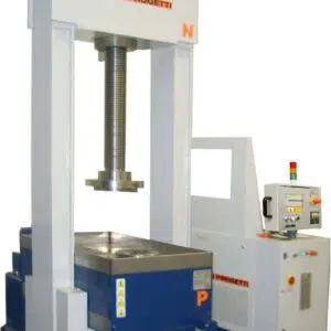
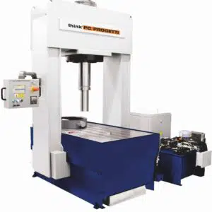
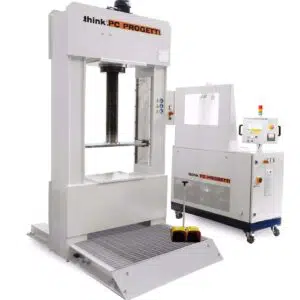
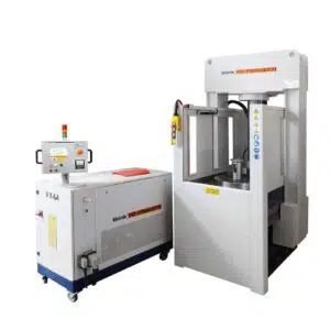
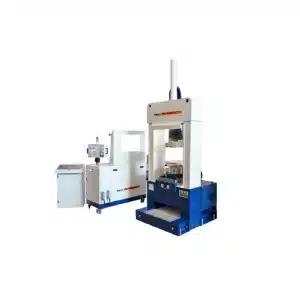
BV-PMC/2000
Vertical test benches with mobile bridge and proportional press clamping. Press force is controlled automatically and proportionally to rising pressure inside... -
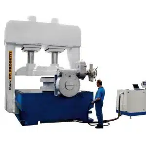
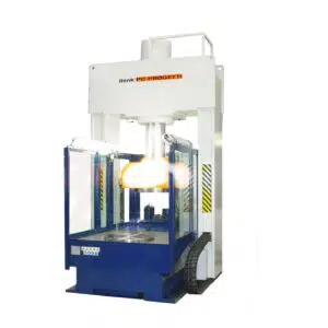
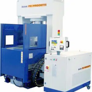
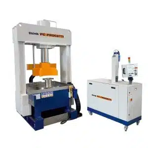
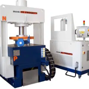
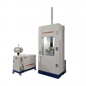
BV-PMC/1200
Vertical test rig with controlled pressing clamp; the press force is according controlled automatically to the water pressure inside the... -
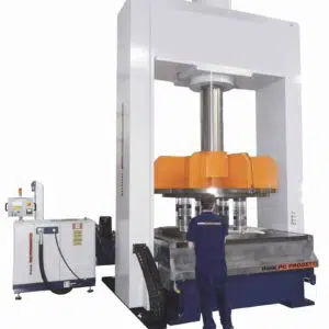
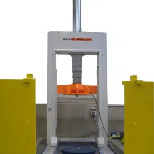
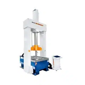
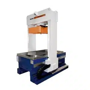
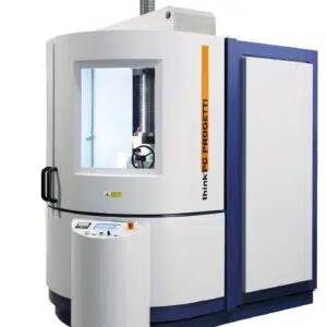
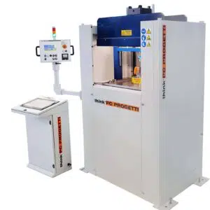
BV-PMC/900
Vertical test benches with mobile bridge and proportional press clamping. Press force is controlled automatically and proportionally to rising pressure... -
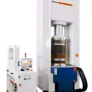
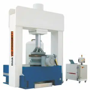
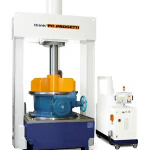
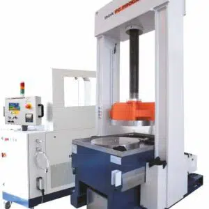
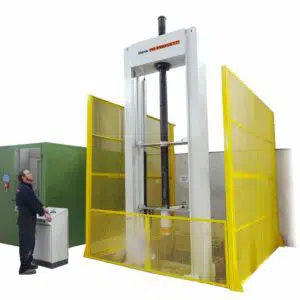
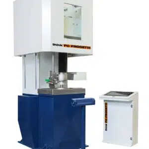
BV-PMC/800
Vertical test rig with controlled pressing clamp; the press force is controlled automatically according to the water pressure inside valves,... -
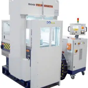
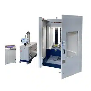
BV-PMC/650W
The mobile upper side bridge allows vertical loading of valves and the possibility to have double working stands; while the... -
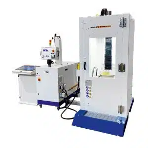
BV-PMC/650
Vertical test rig with controlled pressing clamp; press force is automatically controlled according to the water pressure inside valves, and... -
BV-PMV/600
Vertical test rig with inner radial seal clamping style. The mobile reaction bridge is moved by one screwed column that... -
BV-PMC/550
Vertical test rig with controlled pressing clamp; the press force is controlled automatically according to the water pressure inside valves,... -
BV-PMC/500
Vertical test rig with controlled pressing clamp; press force is automatically controlled according to the water pressure inside valves, and... -
BV-PMC/500S
Vertical test rig with controlled pressing clamp; press force is automatically controlled according to the water pressure inside valves, and... -
BV-PMC/400
Vertical test rig with controlled pressing clamp; press force is automatically controlled according to the water pressure inside valves, and... -
BV-PMC/350
Vertical test rig with controlled pressing clamp; the press force is controlled automatically according to the water pressure inside valves,... -
BV-PMV/350
Vertical test rig with inner radial seal clamping style. The mobile reaction bridge is moved by one screwed column that... -
BV-PMC/250
Vertical test rig with controlled pressing clamp; press force is automatically controled according to the water pressure inside valves, and... -
BV-PMC/200
Vertical test rig with controlled pressing clamp; press force is automatically controlled according to the water pressure inside valves, and... -
BV-PMV/200
Vertical test rig with bore plugs clamping style; mobile upper side bridge allows vertical loading of the valve and the... -
BV-PMC/200-2
Vertical test rig with controlled pressing clamp; press force is automatically controlled according to the water pressure inside valves, and... -
BV-PMC/200SP
Vertical test rig with controlled pressing clamp; press force is automatically controlled according to the water pressure inside valves, and... -
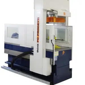
BV-PMC/200SH
In the basement there is a water vessel and an external water vessel could be added as option. The use of... -
BV-PMC/200LP
Vertical test rig with controlled pressing clamp; press force is automatically controlled according to the water pressure inside valves, and... -
BV-1V/200
Vertical test rig with inner radial seal clamping style. The mobile reaction bridge is moved by one screwed column that... -
BV-V/200SH
Vertical test rig with combined clamping style: inner radial seal. The upper side plateau is moved by a screwed column... -
BV-V/100SH
Vertical test rig with combined clamping style: inner radial seal. The upper side plateau is moved by a screwed column... -
BV-PMC/100-2P
Vertical test rig with controlled pressing clamp; the press force is controlled automatically according to the water pressure inside valves,... -
BV-PMC/100SP
Vertical test rig with controlled pressing clamp; press force is automatically controlled according to the water pressure inside valves, and... -
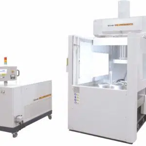
BV-PMC/100S
The rig is controlled by a SKA-100 pressurization skid; to have more information about it please consult dedicated technical data sheets. The... -
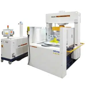
BV-PMMV/100SH
Vertical test rig with universal clamping system; all valve termination kinds and even 90° shape valves can be clamped. In... -
BV-PMCV/100H
Vertical test rig with combined clamping style : inner radial seal and proportional press clamping facilities. The upper side screw... -
BV-CV/100
Vertical test rig with combined clamping style: inner radial seal and press clamping facilities. The mobile reaction bridge is moved... -
BV-CV/100SH
Vertical test rig with combined clamping style: inner radial seal and press clamping facilities. The mobile reaction bridge is moved... -
BV-C/30SH
Vertical test bench with proportional press clamping. Valve clamping is performed by an hydraulic cylinder with proportional control. -
BV-CCV/20P
Fully automatic vertical test rig with controlled pressing clamp; press force is automatically controlled according to the water pressure inside... -
BV-V/20
Vertical test rig with inner radial seal clamping style. The mobile reaction bridge is moved by one screwed column that... -
BV-CCV/15P
Vertical test rig with an automatic test sequence. Combined clamping style: proportional press clamping and inner radial seals. A protection... -
BV-M/7.5SH
Test rig with claws clamping. Test on RF or RTJ valves can be executed in real working conditions. The clamping...